Introduction – pipelines and their personalities
Every pipeline has its own personality and behaves differently. No single leak detection technology is the best solution for every type of pipeline. Large diameter pipelines have come under greater scrutiny from regulators. Environmental activists become ever more strident in their objection and obstruction to these pipelines. Recent large spills from high-profile, large diameter pipelines in North America fuel this unwelcome attention.
This paper offers examples of the diverse challenges for different leak detection systems (LDS) installed on large diameter liquid or gas pipelines. Pipeline diameter is one variable that affects the performance of an LDS, others include configuration, topology, telecommunication, instrumentation, and modes of operation. The high volume of product flowing through large diameter pipelines can make effective leak detection difficult, especially in gas pipelines where the pipeline can behave like an enormous balloon where increases and decreases in pressure and flow at one point may not be reflected in distant parts of the pipeline for hours.
When transporting enormous volumes of product even a small leak for a short period can cause a significant loss of containment. Flow meters for large diameter pipelines are extremely expensive, and if they do not work well, it is hard to convince management to replace them. Too much uncertainty in the flow measurement reduces the reliability of a leak detection system. When this happens, tuning it may require a reduction in sensitivity to improve the reliability of the LDS.
Depending on the variables such as those mentioned earlier, the best leak detection system for assorted pipelines can be different, and the performance of the leak detections systems on various pipelines can be as diverse as the pipelines themselves. The following case studies look at the performance of several leak detection technologies on different pipelines with one common factor: their large diameter.
Case 1: 42-inch crude oil pipeline, 320km (199 miles) long
The large diameter of this crude oil pipeline made it prohibitive to purchase flow meters just for leak detection. Instead, the client installed a negative pressure wave leak detection system. The flow rate in the pipeline varies between 5100 m3/h and 9400 m3/h, depending on the season and the type of crude transported. Flow is in one direction only and there is one intermediate pump-station. The high-volume throughput makes fast leak detection critical.
The leak detection vendor provided a turnkey solution including the data acquisition hardware, VSAT, 3G communication, cabinets and pressure sensors.
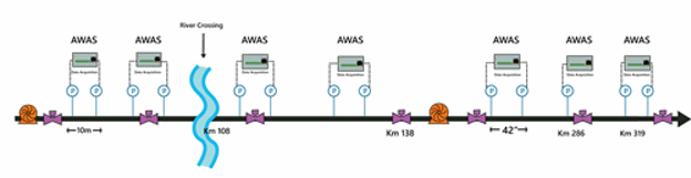 Figure 1: Layout of the pipeline in case 1
Challenges
With operator confidence specified as extremely important, the operator required a highly reliable system. The considerable variations in the viscosity of the crude batches greatly altered the speed at which the pressure waves traveled inside the pipeline, making leak location more complicated. Lack of power and communications in remote areas limited the location options to place pressure sensors. Elevation changes along the pipeline caused vapor pockets.
Performance of the leak detection system in case 1
The pressure sensors were spaced based on the availability of power and communications along the pipeline. When the leak detection system was first installed, the high attenuation of the pressure waves inhibited the system from meeting the agreed performance criteria. The vendor improved the LDS to meet the specified performance by adding additional intermediate pressure sensors in the longer sections. These additional pressure sensors had to be installed in remote areas with no power or communications. This leak detection vendor had a complete line of hardware designed to work with the vendor’s LDS software, including solar panels, to supply the LDS supporting components.
With a system reliability objective of 2 false alarms per year, the system was tuned to a minimum detectable leak size of 0.5% of flow rate in less than 5 minutes. The accuracy of the leak detection system on this pipeline was set to be +/- 200 meters.
In the product withdrawal trials of the Site Acceptance Test, all leaks generated were 2% of nominal flow rate or less, and they were all detected. Leaks as small as 0.2% were detected in some sections of the pipeline. During the final tuning stage this system detected and located a theft event further reinforcing the end-user’s confidence in the system.
Case 2: 42-inch crude oil pipeline from a marine terminal to a refinery
The changing operations on a 15 km (9.3 mile) long, 42-inch diameter crude oil pipeline with one inlet and two outlets on the West Coast proved too challenging for reliable volume balance leak detection because of the inaccuracy of the flow meters.
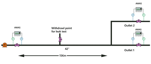 Figure 2: Layout of the pipeline in case 2
Challenges:
Reclaiming pipeline controller confidence, the previous, SCADA-based modified-volume balance system issued too many false leak alarms. The flow meters failed to maintain accuracy and repeatability.
Performance of the leak detection system in case 2
The operator decided to install the Wave Flow leak detection system which combines the high reliability and accuracy of the modified mass balance elements with the proven sensitivity and accuracy of the negative pressure technique. High resolution pressure sensors were installed at each end of the pipeline and the Wave Flow system was configured to use data from these sensors and from the existing flow meters. The meters were connected to the high-speed data acquisition units installed at each end of the pipeline to pass the flow data back to the leak detection server.
The Wave Flow system was tested by diverting part of the flow into an unmetered delivery to a storage tank half-way along the pipeline. The test began with the field personal opening the valve at the midpoint off-take first to fill the line to the storage tank. The valve at the tank was then opened and controlled to allow a measured product withdrawal rate. The valve was opened and adjusted to allow a leak that was 3% of the nominal flow rate.
The Wave Flow system issued a leak alarm in just under 3 minutes and provided an accurate leak location. This performance significantly exceeded the quoted detection time of 5 minutes.
An additional test was performed at a higher leak rate of 10%. The Wave Flow system issued a leak alarm for this withdrawal rate in just under 1 minute and provided an accurate leak location.
The Wave Flow leak detection system uses both volume balance and rarefaction wave methods. The system uses a multi-element model to reduce uncertainty and improve performance. This assures reliable, accurate leak detection and location in a significantly faster time. The availability of tailored hardware such as sensors and high-speed data acquisition units with built-in communications make this system ideal for existing pipelines, especially pipelines that lack instrumentation, power or communications.
Case 3: Baku-Tbilisi-Ceyhan (BTC) Pipeline1
The 1768 km (1,099 miles) long BTC crude oil pipeline runs from Sangachal Terminal near Baku in Azerbaijan, via Tbilisi in Georgia, through Turkey to a new export terminal located near Ceyhan on the Turkish Mediterranean coast. The pipeline has seven intermediate pump stations and routes through some mountainous terrain, rising to more than 2,500m in Georgia and 2,800m in Turkey, remaining above 1,500 m until near KP 1,650 in Turkey where it descends to the Mediterranean Sea.
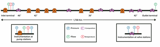 Figure 3: Layout of the pipeline in case 3
The pipeline is 42-inch in diameter except for the 46” section through Georgia and a 34” section in Turkey. There are several areas of slack (vapor pockets) in Turkey that make effective leak detection challenging.
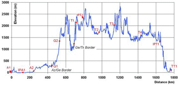
Figure 4: BTC Pipeline Elevation Profile
This line was well instrumented with flow and pressure measurements. The statistical volume balance (SVB) method was configured for several discrete sections to optimize the performance and provide redundancy:
- Three main “country’ sections – Azerbaijan, Georgia and Turkey
- Seventeen sub-sections where flow measurement is available
- One overall section that monitors the entire length of the pipeline
Challenges
The extreme elevation changes as the pipeline climbs and descends over mountains cause several areas of slack, complicating leak detection. The operator committed to the partners, lenders, NGO’s and other stakeholders to provide the highest possible performance in leak detection from the moment when hydrocarbons were introduced into the pipeline. In the absence of prior operational data, and with the pipeline partially filled, it was challenging for the LDS to monitor the integrity of the pipeline throughout the whole filling process. After the pipeline was commissioned there were problems with the flow meter accuracy and repeatability. Pigging and surge relief operations add further challenge to the support of the leak detection system.
Performance of the leak detection system in case 3
The statistical volume balance leak detection system uses the Statistical Probability Ratio Test (SPRT), a hypothesis testing method on the inventory compensated volume balance data, to decide between a leak and no-leak scenario on the pipeline. The SPRT calculates the ratio of the probability of a leak over the probability of no-leak and decides if the corrected volume balance has increased with a predetermined probability, e.g. 99% 2. With the additional flow and pressure instruments along the pipeline, the performance of each section is individually optimized. For example, the slack sections are isolated so that the liquid-filled sections can maintain the best performance all the time. The LDS has been an integral part of the BTC operations since 2006 and the following performance figures are applicable to most sections:
- 0.5% Leak Detection Time: 58 to 160 minutes
- 1.0% Leak Detection Time: 19 to 30 minutes
- 10% Leak Detection Time: 1 minute.
Case 4: 42-inch diameter, 700 km (425 miles) long gas pipeline
The 42” pipeline carries natural gas from a processing station to an export terminal, crossing two different countries at elevations ranging from near sea level to almost 2,500m. The pipeline has 11 block valve stations with pressure sensors. The SCADA system transmits pressure, flow, temperature, and valve status data at a 5-second refresh rate to the leak detection system via OPC. This includes data from custody transfer flow meters at the injection, at two border crossings, and at the delivery points. Pressure and temperature data are transmitted from the receipt and delivery points and from all block valves. Fuel gas flow meters and pressure sensors are also available at the fuel offtakes.
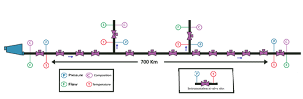
Figure 5: Layout of the pipeline in case 4
Challenges
The shortest distance between instrumented block valves or offtakes is 14 km, and the longest distance between instruments is about 90 km. The leak detection and location performance is better for the shorter sections. The main challenge for gas pipeline leak detection is the compressibility of gas and the packing/unpacking operation. A 2% leak has very little impact in a pipeline with a total volume of 625,325 m3. Tuning of each section using pressure meter readings is important to achieve the sensitivity required.
Performance of the leak detection system in case 4
The typical performance of the statistical volume balance LDS in the short segments of this pipeline ranges from the detection of a 2% leak within 10 minutes to detection of a 20% leak within 1 minute. The typical performance of this system in the long segments ranges from detection of a 2% leak within 120 minutes to detection of a 20% leak within 12 minutes. This is a good example of how leak detection performance is very much dependent on the distance between the flow and pressure sensors. This is particularly relevant in a gas pipeline because the pressure waves travel much slower in gas than in liquid.
Case 5: 560km (348 miles) long gas pipeline, 32-inch and 36-inch diameter, mainly offshore
The statistical volume balance leak detection system is installed on a 560 KM long pipeline with external diameters of 32-inches and 36-inches with four supplies and two deliveries to a LNG Plant.
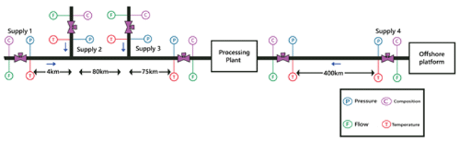
Figure 6: Layout of the pipeline in case 5
Challenges:
Over 400 km (249) of this gas pipeline system is subsea. Being subsea, this section has only 2 pressure sensors, one on the platform and one where the pipeline comes ashore. If a leak occurs in the middle of the offshore section, it will take over 7 minutes for the pressure wave to reach the sensors. If the leak occurs on the offshore end of the pipeline, the pressure wave from the leak can take over 14 minutes to reach the onshore pressure sensor. The pipeline never shuts down, so the data shows long periods of pressure packing into the pipeline followed by periods where it unpacks when the injections stop. It is difficult to quickly detect a leak with high reliability under such conditions. Significantly longer detection time must be configured on this pipeline segment to avoid false leak alarms.
Performance of the leak detection system in case 5
The Statistical volume balance leak detection system is configured to a sensitivity that ranges from detecting a 12% in 180 minutes to a 40% leak in 15 minutes and has proven highly reliable, issuing very few false leak alarms in its 4 years of operation. The sensitivity of the LDS is curtailed by the large separation (over 400-km) between the pressure sensors on the offshore segment of the network, by the continuous transient operations and low flow meter accuracy.
Conclusions
The above five case studies present five very different, large diameter pipelines, each with its own personality and challenges. This shows that leak detection performance can be very different from one pipeline to another, depending on variables such as diameter, configuration, topology, telecommunication, instrumentation, and modes of operation. Given the enormous volumes of product transported in large diameter pipelines even a small leak for a short time can result in a large release. However, even though the sensitivity and detection time of a leak detection system are very important factors, they can be very much curtailed by the laws of physics as applied to pipelines. The number and type of sensors and how they are spaced can strongly influence the leak detection time and location accuracy especially in long, large diameter, gas pipelines.
References
- Willliams G., Welsh A., of BTC Company, Mabe J., Murphy K., of Atmos International. "Commissioning a Real-time Leak Detection System on a Large-Scale Crude Oil Pipeline During Start-up". ASME International Pipeline Conference. Calgary, Canada. 2006.
- Zhang J., Twomey M., Introduction to Pipeline Leak Detection Systems 1st ed. Manchester [England]: Creative Design, 2017. Print & Kindle.