When single phase becomes multiphase: the challenges for pipeline simulation
A number of single phase pipelines experience multiphase flow operations e.g. slack flow in liquid pipelines when vapor pockets form at high points.1 Most single phase pipeline simulators lack the advancements to model anything beyond a single phase. For experts in the field, pipelines operating in a multiphase flow can make even a steady state calculation difficult.
Liquid pipelines sometimes operate in slack-line rather than being kept consistently tight, whereas on other pipelines, column separation might not be as frequent. Wet gas pipelines could have liquid drop-out when the flow-rate reduces.
Avoiding liquid drop-out
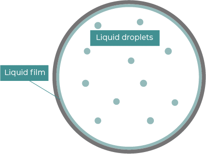
Figure 1: An example of liquid drop-out in a gas pipeline cross-section. During increments of high flow, the fuel will form spray in the center of the line and a liquid film around its circumference, with the film becoming thicker at the bottom of the pipe’s circumference
When natural gas flows down a pipeline there is a frictional loss that causes a pressure drop. This causes the Joule-Thomson effect and the gas starts to cool down along the pipeline route. The temperature decrease could result in liquid drop-out.
A big change in state from a vapor to a liquid is a massive event for the molecules in the pipeline and can cause knock-on effects. On a natural gas pipeline, for example, water and some of the heavier hydrocarbons can drop out, reducing the volume occupied by the fluid and carry a risk of forming hydrates. Violent transients can appear if slugging takes place too.
Given that liquids drop out of a gas at different rates because of factors like temperature and retrograde condensation, natural gas pipeline operators need to consider liquid drop-out as part of their operations. Rich gas is particularly at risk in this case while pipelines from wellheads to a gas processing plant have facility to handle liquids.
Wet gas pipelines: simulating multiphase using a single-phase model
In a wet gas pipeline, multiple operational conditions can result in the fluid being separated into three phases: gas, condensate and water. While a full multiphase simulation can track these elements separately, a single-phase model can be effectively used to accurately simulate pressure, flow and temperature.
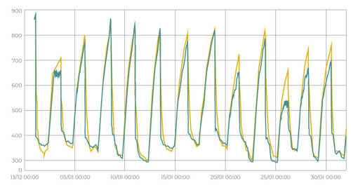
Figure 2: Liquid volume (m3) in a wet gas pipeline over time, estimated by Atmos SIM’s accumulator model (blue) and compared against the multi-phase model’s forecast (red)2
To effectively simulate a wet gas pipeline using liquid hold-up like in Figure 2, the liquid needs to stay stratified, avoiding slugging or accumulation at low points, and there must be no sudden changes in operation. If these conditions are met, liquid hold-up can be simulated without vapor-liquid equilibrium calculations.
Vapor-liquid equilibrium
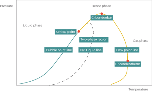
Figure 3: Diagram illustrating the process a multiphase natural gas pipeline goes through. It includes a liquid phase, vapor phase (gas phase), supercritical phase (dense phase) and a phase envelope (a two-phase step signaled by the bubble point line and the dew point line)
Most pipelines run within the liquid phase, gas phase or vapor phase conditions, but there are always exceptions.
The supercritical phase
The dense phase, sometimes understood by its name of supercritical phase, is a point where the pipeline is operating at a pressure and temperature above the critical point. Ethylene and carbon dioxide pipelines are common examples which run at the supercritical phase.
Changes of phase
Two common phenomena can occur in a pipeline which result in partial changes of phase. For example, slack in liquids can evaporate some of the liquid product into the vapor phase and drop-out in a gas product can condense gas into the liquid phase.
Simulating slack in a liquid pipeline
We need only take our thumb off the edge of a straw to drain the liquid to see how quickly it mixes with air, and if you replace the straw in this scenario with a pipeline the results will be similar.
Air pockets are a common occurrence in water pipelines, so it’s almost a guarantee that there will be dissolved gases in water moving through a pipeline. Vents are often installed along a water pipeline to release air from the solution in large quantities.
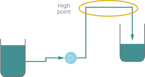
Figure 4: A scenario in a water pipeline in which air is likely to increase (an isolated high point)
If the same process occurs for a hydrocarbon liquid like a refined product or crude oil and it has been exposed to air, there will be air dissolved in the product and it will behave in a similar way to water with air in it.
The fluid itself might also change phase, with a portion of it moving into the vapor phase. Looking at a hydrocarbon’s Reid vapor pressure (RVP) can assist in modeling the multiphase flow in a pipeline at specified conditions. The true vapor pressure (TVP) of the same liquid mixtures could differ for many reasons, such as the true vapor pressure being a function of temperature while the RVP is a fixed measurement at 37.8 degrees Celsius.
Simulating multi-phase flow
Pipeline simulation software models of multiphase flows must be accurate for the simulation to be correct. It’s a specialist topic which is common in upstream gathering lines.
Multiphase flows can be two phase and involve oil and water, oil and gas or water and gas or three phase or even four phase. They often stratify into a pattern of distinct layers and are likely to need routine pigging to remove wax and liquid slug build-up.
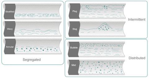
Figure 5: The multi-phase flow regimes in a pipeline, including segregated, intermittent and distributed
Multi-phase flow regimes are harder to measure than a single-phase flow because there could be a stratified, slugging or bubbly interface occurring in the pipeline at any given moment.
Although a well tuned single-phase model can perform leak detection effectively and incurs a lower cost, a two phase, three phase or even four phase physical model has the potential to perform leak detection better if it is tuned well to match actual operations.
Download chapter 13 Order the book
References
1 “The Atmos book of pipeline simulation”
2 Modelling & Simulation of Gassco Wet Gas Pipelines PSIG 1604, Hanmer, Basnett, Issak, Rinde